Volumetric calculations
Volumetric calculations combine a reservoir boundary with rock and fluid properties to estimate effective reservoir volume, oil, gas or CO2 volumes. Start from the Reservoir tab.
Calculate gross rock volume
In the GRV group, choose a Polygon and the first Surface as the top depth map. Choose the second Surface when a bottom depth map is needed, or leave it set to Not required when the fluid contact defines the lower boundary.
Enter the Fluid contact depth and click Calculate gross rock volume. The ribbon displays the resulting GRV from Fluid contact and Fluid contact area.
See Reservoir bar for the current ribbon layout and command locations.
Calculate reserves
In the Reserves group, click Calculate reserves. The wizard provides Simple and Advanced modes for Effective reservoir volume, Oil, Gas and CO2.
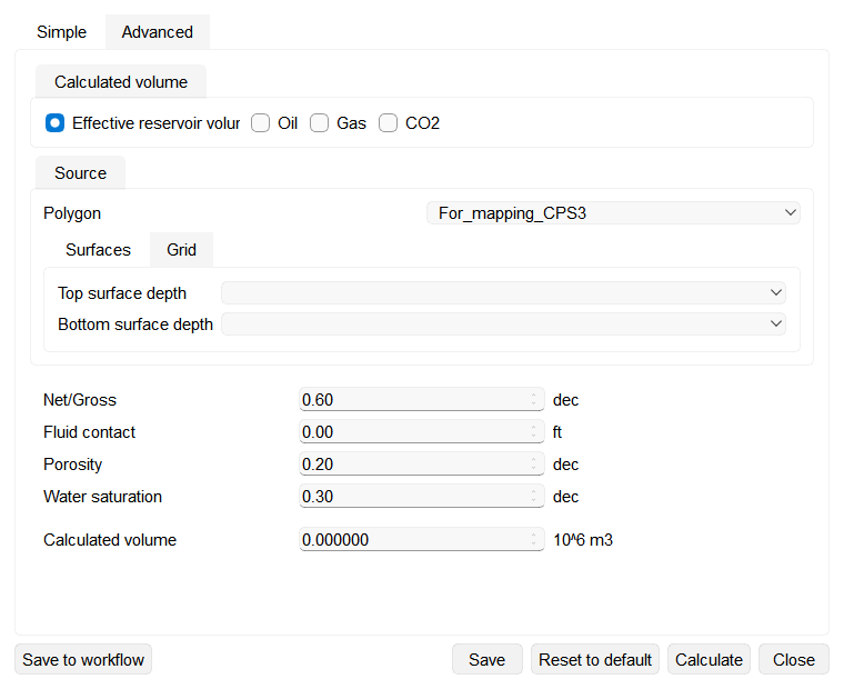
The image shows the Simple Effective reservoir volume layout before the top and bottom depth maps are selected.
Simple mode
- On the Simple tab, select the required Calculated volume.
- Choose the bounding Polygon. On the Surfaces tab, select both Top surface depth and Bottom surface depth. Alternatively, open the Grid tab and select an existing project Grid.
- Enter the rock, contact and fluid parameters displayed for the selected volume type.
- Click Calculate. The result is displayed in the wizard, which remains open for further changes or calculations.
Oil parameters
Selecting Oil replaces the parameters below the Source area with the oil parameters. Each one opens with a standard value: Net/Gross 0.60 dec, Porosity 0.20 dec, Water saturation 0.30 dec, Oil formation volume factor 0.12 v/v, Oil density 0.850 g/cm3 and Recovery factor 0.30 v/v.
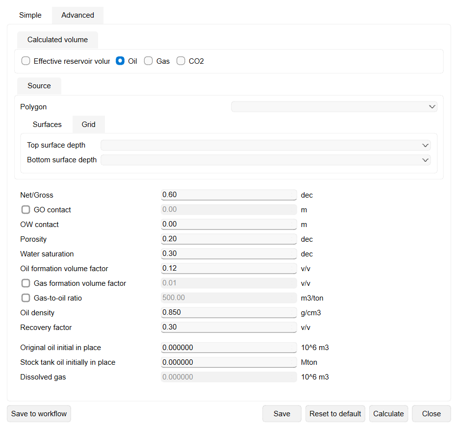
OW contact sets the lower depth limit of the calculated volume. Select the optional GO contact checkbox, which is cleared when the wizard opens, to add an upper depth limit so that only the interval between the gas-oil and the oil-water contact is used. While GO contact is cleared, no upper limit is applied and the volume is bounded by the selected top surface or grid down to OW contact.
Two further checkboxes are also cleared when the wizard opens: Gas formation volume factor 0.01 v/v and Gas-to-oil ratio 500 m3/ton. Selecting a checkbox makes its value available, and the read-only Dissolved gas result stays unavailable until both are selected.
The read-only boxes under the parameter list report Original oil initial in place in 10^6 m3, Stock tank oil initially in place in Mton and Dissolved gas in 10^6 m3. On this page, Reset to default restores the standard values and clears the three optional checkboxes, but keeps the GO contact and OW contact depths you have entered.
Gas parameters
Selecting Gas replaces the parameters below the Source area with the gas parameters. Each one opens with a standard value: Net/Gross 0.60 dec, Fluid contact 0.00 m, Porosity 0.20 dec, Water saturation 0.30 dec, Reservoir pressure 20 MPa, Pressure at standard conditions 0.101325 MPa, Reservoir temperature 350 K, Standard condition temperature 293 K, Compressibility factor 0.80 coeff and Gas formation volume factor 0.01 v/v.
The two read-only boxes under the parameter list report Original gas initial in place and Standard gas initially in place (SGIP), both in 10^6 m3.
CO2 parameters
Selecting CO2 replaces the parameters below the Source area with the CO2 storage parameters. Each one opens with a standard value: Net/Gross 0.60 dec, Fluid contact 0.00 m, Porosity 0.20 dec, Water saturation 0.30 dec, Reservoir pressure 20 MPa, Pressure at standard conditions 0.101325 MPa, Reservoir temperature 350 K, Standard condition temperature 293 K, Compressibility factor 0.80 coeff, Gas formation volume factor 0.01 v/v, CO2 storage efficiency factor 0.75 coeff and Residual gas saturation 0.20 coeff. Change the values that differ for the storage site before you calculate.
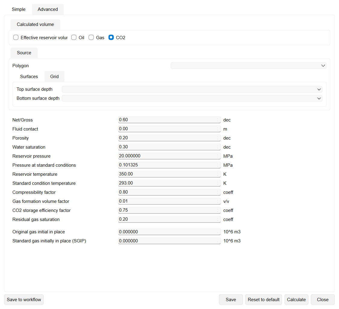
The CO2 page reports the same two read-only results as Gas: Original gas initial in place and Standard gas initially in place (SGIP), both in 10^6 m3. They stay at zero until Calculate runs, and Reset to default restores the standard values on the page while keeping the Fluid contact depth you have entered.
Advanced mode
The Advanced tab performs a stochastic estimate and reports percentile results. It uses the polygon selected on the Simple tab together with the depth-map limits configured in Surface maps.
- Set Number of Realizations and Smoothing radius (grid nodes). Enable Fixed seed when the same random sequence must be reused.
- For Top Surface Depth, choose Upper limit and Lower limit maps. Do the same for Bottom Surface Depth, or clear Active when no bottom surface is used.
- Define the distributions for the parameters shown for the selected volume type. Enable Correlation matrix when correlations between inputs must be included.
- The Calculated volume (percentiles) panel reports P99, P90, P50, P10 and P1. Sensitivity analysis is available for Effective reservoir volume only.
Run, save or add to a workflow

- Save to workflow adds a Calculate reserves job with all current settings to the current workflow. It does not run the calculation, and the wizard remains open.
- Save stores the current wizard settings and closes the wizard.
- Reset to default restores the standard parameter values for the active calculation mode.
- Calculate runs the calculation without closing the wizard.
- Close closes the wizard without saving the current changes.
When a saved Calculate reserves job is opened from Workflows, its saved mode, source and parameters are restored. The footer then shows only Save and Cancel: use Save to update the job or Cancel to leave it unchanged. Executing the workflow runs the calculation with the stored settings.
Create a geo-body
To create geometry from the current GRV inputs, use Create geo-body from gross rock volume in the Geo-body group. For the broader structural-model workflow, use Create 3D geological model and see Geological modeling.
See Also