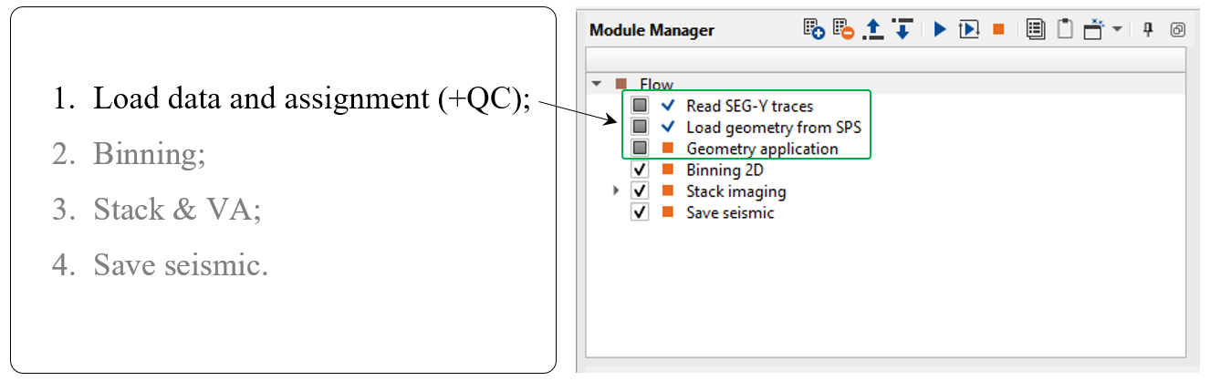
The geometry assignment and QC for land project consist of the following main modules that are used together:
1. Read SEG-Y traces - load trace headers and amplitude samples from the input seismic data set;
2. Load geometry from SPS - load navigation files like SPS for land or UKOAA/P190 for marine acquisition, QC;
3. Geometry application - write navigation files into traces headers of seismic traces, QC.
Block scheme (left) and workflow (right):
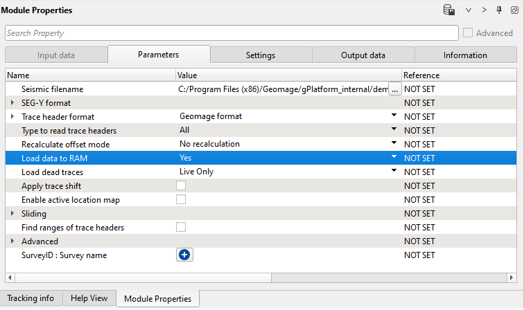
Read SEG-Y traces module loads trace headers and seismic samples to the current workflow and other modules use it for further processing. In the module's parameters we need just select the input file Seismic filename parameter and launch the job by double click on the module or click on button ![]() . Pay attention on the Load data to RAM parameter, i.e. if we have enough RAM for loading seismic data into memory, so it is reasonable to use Yes option, in that case we are able to save seismic data directly from the RAM into the data base, otherwise we should use Seismic loop module for saving resulting seismic data set with geometry:
. Pay attention on the Load data to RAM parameter, i.e. if we have enough RAM for loading seismic data into memory, so it is reasonable to use Yes option, in that case we are able to save seismic data directly from the RAM into the data base, otherwise we should use Seismic loop module for saving resulting seismic data set with geometry:
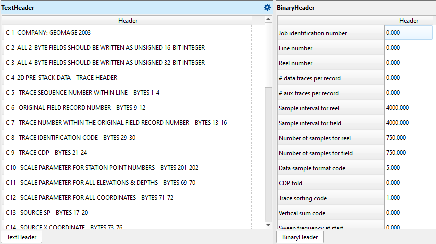
Trace headers were read from the SEGY file and it is possible to check EBCDIC, binary and trace headers:
![]() If we need to visualize more input data (QC windows) from SEGY file it is reasonable to use View SEG-Y module.
If we need to visualize more input data (QC windows) from SEGY file it is reasonable to use View SEG-Y module.
------------------------------------------------------------------------------------------------------------------------------------------
![]() WARNING about reading SEGY files! If the input seismic data is SEGY file:
WARNING about reading SEGY files! If the input seismic data is SEGY file:
Do not save seismic from SEGY into internal data base before geometry assignment!!! (i.e. do not use Save
seismic / Save seismic by gather).
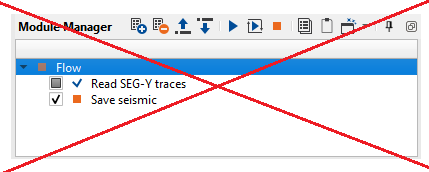
Otherwise, you will lose some trace header information! Therefore ,we must use Read SEG-Y traces, prior
to geometry modules. You should assign geometry before saving traces in DB.
-----------------------------------------------------------------------------------------------------------------------------------------
2. Load geometry from SPS
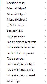
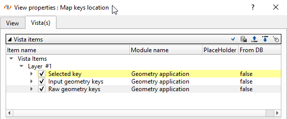
This module imports SPS files from ASCII into the processing system. There is an option for displaying source and receiver coordinates on the map, S, R, X spreadsheets (tables), inconsistency between SPS files via error tables, source and receiver elevation graph. All the navigation information is shown on visual windows and tables. Location map and SPSElevation windows have a few layers with source and receiver information that we can set up: change color, point size, hide/show. There is a list of all vista windows from this module that we can open:
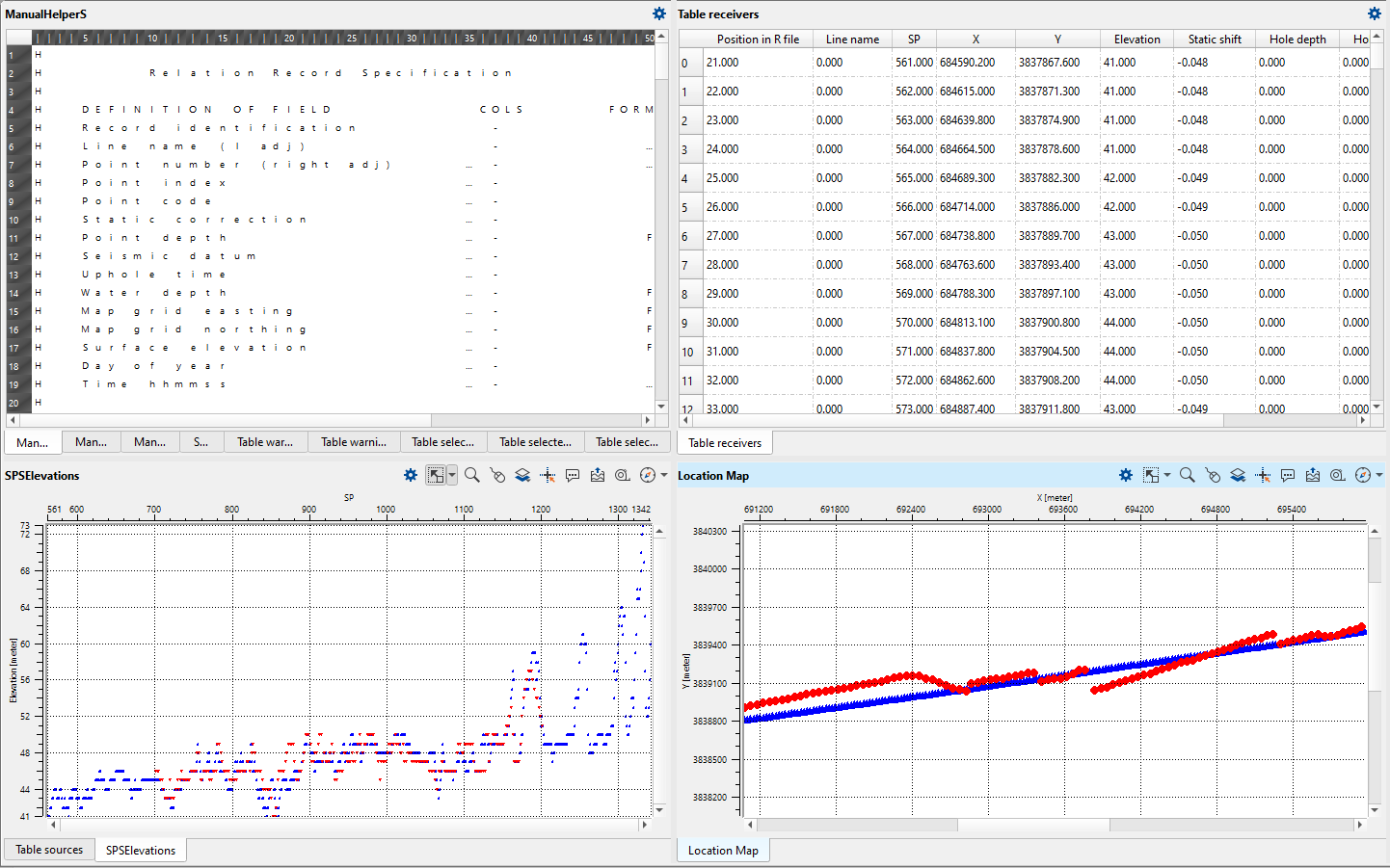
Below a set of vista windows where we can check all the navigation information: EBCDIC header, elevation graph (receiver and source), S, R, X files:
This module is designed for assigning geometry on land and marine 2D/3D seismic data, checking geometry, also manual trace editing is implemented there. The trace headers are filled in accordance with input geometry files, but without binning (binning will be perform on the later stage by using binning 2D/3D modules). The process of geometry assignment is divided into three following steps:
1) Loading geometry files using the Load geometry from SPS;
2) Geometry assignment (Connect geometry from the Load geometry from SPS and the original file trace headers and SEG-Y data handle);
3) QC, correction of applied geometry and optional trace editing.
-----------------------------------------------------------------------------------------------------------------------------
![]() Geometry Application is a standalone module, and does not need to be run inside a Seismic loop.
Geometry Application is a standalone module, and does not need to be run inside a Seismic loop.
-----------------------------------------------------------------------------------------------------------------------------
Connect all necessary input DataItems for Geometry application as it is shown below:
Input data:
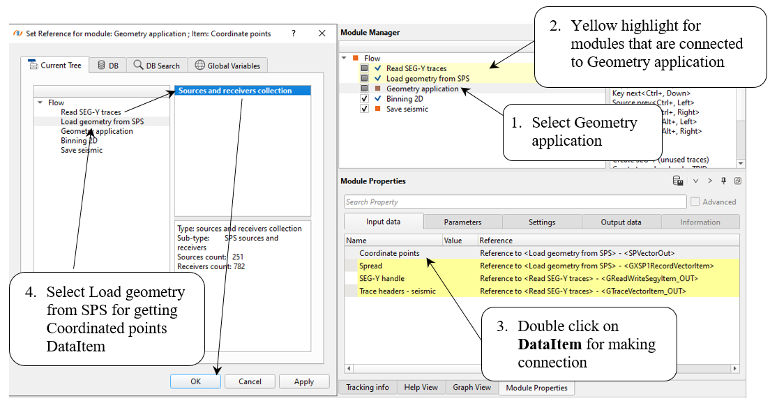
You may click on any entry in a table, or any location on a map, and that point will be highlighted or displayed in all other views. Use the Table Errors Vista to check mis-matches between geometry files and the seismic data set;
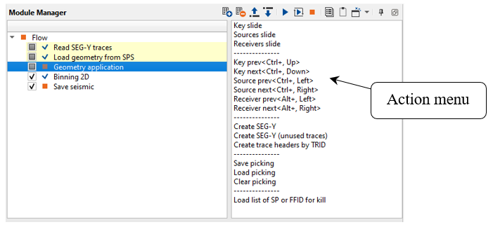
•Use the Action Items associated with Geometry application to view the shots, receivers and field files in auto-mode/movie (Key slide, Sources slide, Receivers slide) or one by one (Key prev, Key next, Source prev, Source next, Receiver prev, Receiver next);
--------------------------------------------------------------------------------------------------------------------------
![]() Not every module has an action menu. Only advanced modules like application or interactive
Not every module has an action menu. Only advanced modules like application or interactive
have an action menu.
-------------------------------------------------------------------------------------------------------------------------
•Click on the Map and Table views to view the gathers at particular location:
There is another convenient tool for trace number comparison:
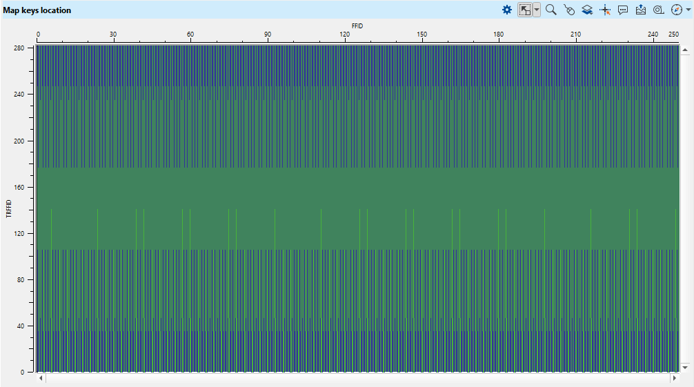
There are two layers: seismic and geometry. If we don have geometry for some seismic gathers it will be easily detected:
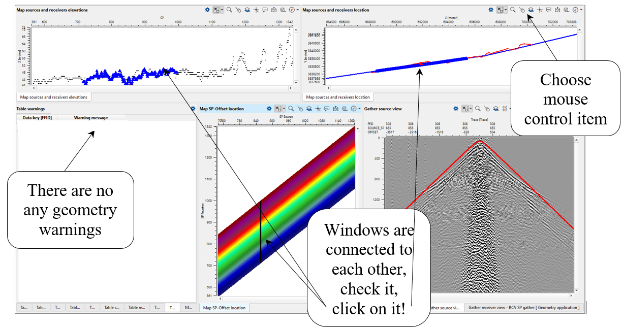
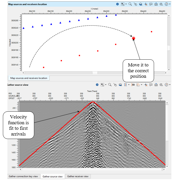
Go through all source gathers and check geometry by comparison first arrivals on traces with the linear velocity function (red line), check the offset distribution on the Map SP-Offset location window, look at all tables and make sure you don't have any critical problem with geometry.
What we have on display:
•Table Errors - vista displays mismatches between the original seismic file and geometry files;
•Table Changed Points - displays points that have been moved, including their new and former positions;
•Table Spread, and Table FFID RAW - display the spread/relation and raw FFID numbers respectively;
•Table Sources, and Table Receivers - display the source and receiver numbers and its coordinates. You may remove shots or receivers (mark all the traces as dead) by right clicking on that entry in the table and selecting Kill Shot or Kill Receiver;
•Table Killed Sources, and Table Killed Receivers - display all the shots and receivers killed (marked as dead) by the user. Killed shots or receivers can be revived by right clicking on an entry in these tables and selecting Revive.
Map views include:
•Map FFID location, Map Sources and receivers elevations and Map SP-Offset location, which display various cross plots of geometry characteristics;
•Map Sources and Receivers Location display location of shots and receivers on a map, allow to move those points from one location to on another if necessary. See Moving Points. Use these views to verify positions of sources and receivers and move them (see moving points).
You may move the physical location of a shot or receiver point on the map by using the Map Sources and receivers location.
Use the ![]() button on the vista tool bar for the Map Sources and receivers location Vista, choose Current Source Moving Point and Selected Source.
button on the vista tool bar for the Map Sources and receivers location Vista, choose Current Source Moving Point and Selected Source.
Right mouse click and hold on the source point you would like to move. Drag the point to its new location. The previous location of the source will be indicated by its original marker (default: Red triangle), and the new location will be indicated with new marker (by default, a semi-transparent red circle).
When you move some source point, the Velocity display on the Gather Source view will be updated and it reflects a new source point location.
The source point marker will be updated with its new location when you click on the new point again, or on a different source point.
The new position will also be reflected in the Table Changed Sources.
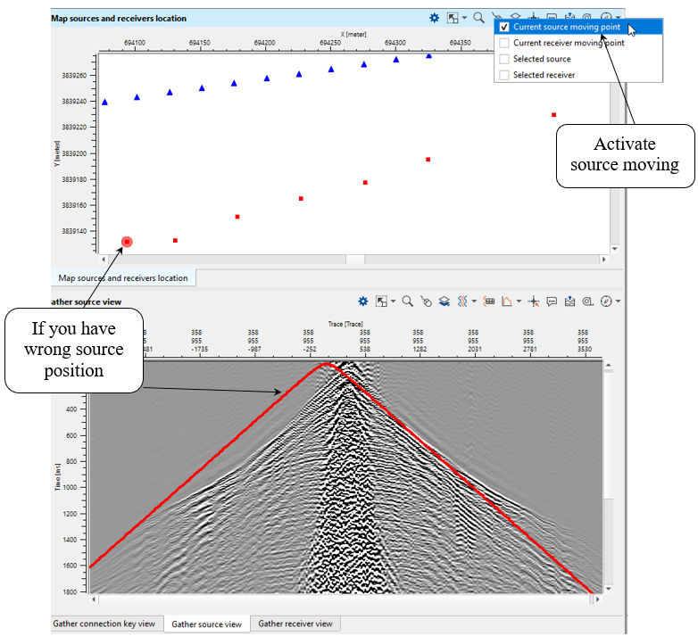
Try to move the point so that the velocity display aligns with the traces on the Gather view. The peak of the velocity function should match up with the nearest first arrivals – this is a good indication that your source point is positioned correctly.
Execute the module. On the output we have updated trace headers with geometry.
 If you have any questions, please send an e-mail to: support@geomage.com