Fault picking
Fault picking is aimed at identifying discontinuities or breaks in subsurface reflectors that indicate faults. The process in g-Space follows core principles similar to those used in Horizon picking but with an emphasis on identifying and mapping structural breaks.
Notes
Methodological Approaches
- Discontinuity Identification Fault picking focuses on identifying breaks or offsets in seismic reflectors. The key steps include:
- Structural Interpretation Faults often follow particular structural patterns, which can help guide the picking process. This involves:
- Seismostratigraphic Context Faults often correlate with stratigraphic markers. Integrating seismostratigraphic information can help refine fault interpretation by linking faults to stratigraphic units, sedimentary processes, and depositional environments.
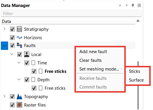
The Data Manager in g-Space organizes fault data into a structured hierarchy that allows users to work within either the Time or Depth domain, depending on the seismic data and the interpretation workflow.
The Local folder is active by default for multi-user mode and the results of interpretation are stored in your local project.
Free Sticks:
Faults can be visualized and manipulated as Free Sticks, representing vertical fault traces along seismic sections. This view allows users to pick fault segments and analyze them in a stick-based representation, which is useful for initial interpretations and quality control.
Surface Mode:
Users can switch from the stick representation to Surface Mode, which converts the fault sticks into continuous fault surfaces. This mode is helpful for visualizing the complete geometry of a fault plane, providing a more holistic view of the fault structure within the seismic volume.
You can define faults in the Map View, 3D View, 2D View, Inline and Crossline Views as well as in the Arbitrary line View.
Picking is not limited to the time domain: depth Inline, Crossline and Arbitrary line sections offer the same Fault picks tool and the same Current fault item as their time counterparts. Each stick keeps its own Time or Depth domain, and a click made on a section in the other domain is converted through the current velocity model, or through the project V0 value when no velocity model is selected, so a time fault can be extended from a depth section and vice versa.
g-Space also provides options to Import faults.
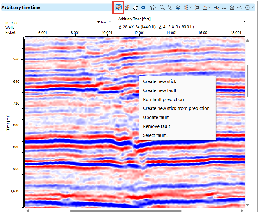
To start fault picking, create a new fault in the Data Manager or directly on the seismic section by pressing Alt + Right Click Mouse with the Fault Picks mode enabled (highlighted in red)
On a time section this menu also offers Run fault prediction, Create new stick from prediction and Create new sticks from all predictions, described in Fault prediction. These three commands are not offered on a depth section.
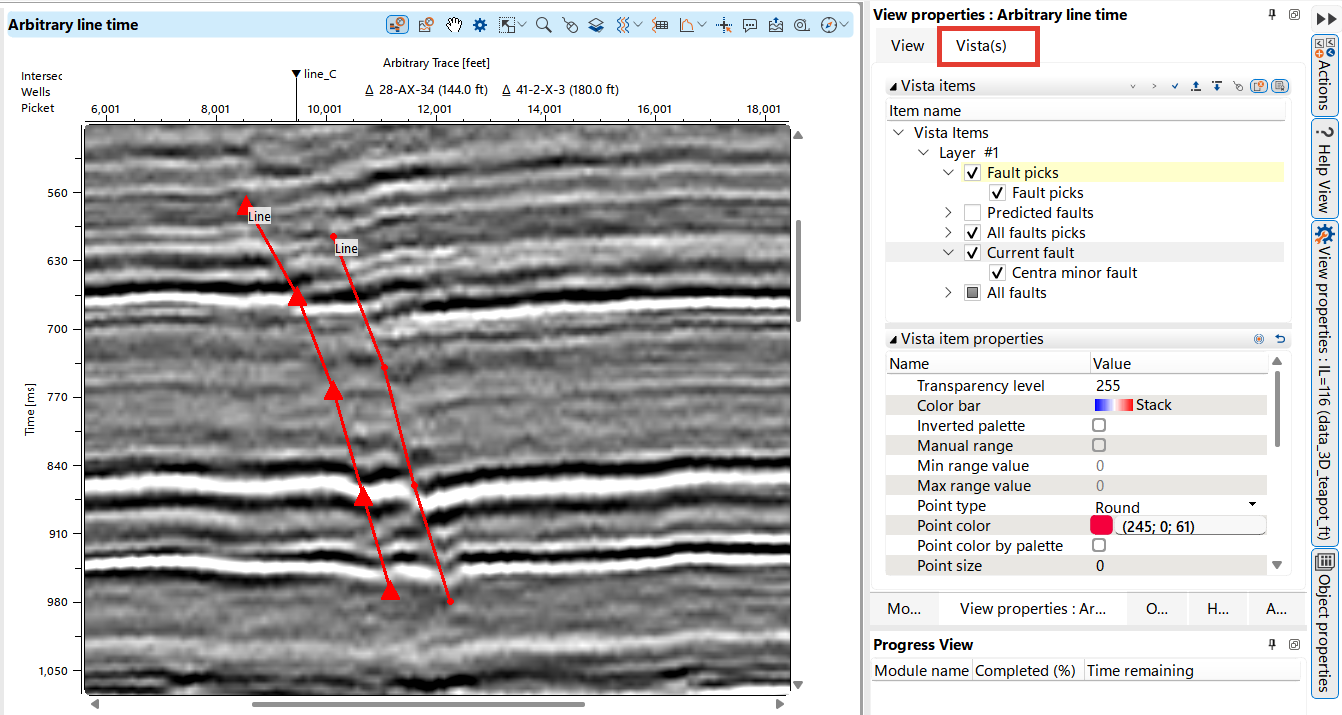
Users have access to various settings for visualizing faults in the Visual Settings panel.
Make the object you want to customize active in the Data Manager, it will appear in the Object(s) tab and visual settings will be available for each element at the bottom of the right area at the Object item properties.
In the image below, a color palette is configured specifically for the seismic section, while the visualization of already picked faults and the current fault is managed separately.
,
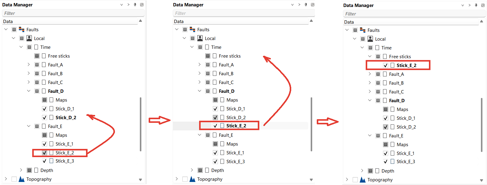
During the fault picking process, the user creates sticks within the folder of a specific fault. If a stick is mistakenly assigned to the wrong fault, the interpreter can easily correct this by selecting the stick with the left mouse button and dragging it to the correct fault folder. In cases where it is unclear which fault a particular stick belongs to during interpretation, the user can temporarily store it in the Free Sticks folder for later assignment.
A fault also stores point sets in its Points folder. To add one, right-click Points under a fault you can edit and choose Create empty point set; the new set appears under Points as PointSet_1, PointSet_2 and so on. Right-click a point set and choose Rename to open the Set name of the point set dialog and enter a new PointSet name, or choose Remove to delete the set. Both commands are offered only for faults you can edit. Point sets are stored with the fault and saved with the project.
Each fault also has a Surface node that holds its triangulated fault surface. Select the Surface check box to draw that surface in the 3D view; it stays in step with the matching item under Fault 3D in the Visual Settings panel. The sticks are controlled by the fault's own check box, so the surface and the sticks can be shown separately or together. To write the displayed surface to a GOCAD TSurf file, right-click Surface and choose Export to GOCAD TSurf; see GOCAD Data Formats.
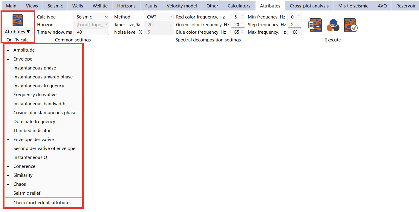
It is a common practice to use seismic attributes to enhance fault identification. While there is an entire chapter dedicated to Attribute analysis, here we will focus specifically on the On fly attributes calculations to aid in fault picking.
In the Attributes Bar, select On fly calculation and select the attribute you need, it will instantly appear on the section you have open.
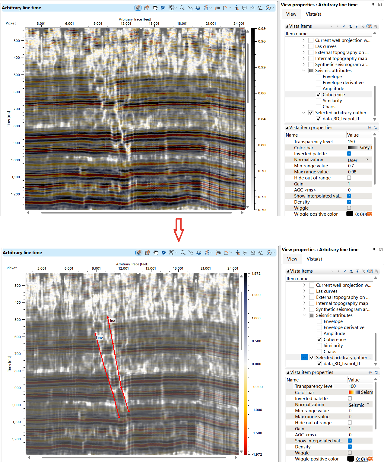
Set up the palette for maximum efficiency and perform a fault pick.
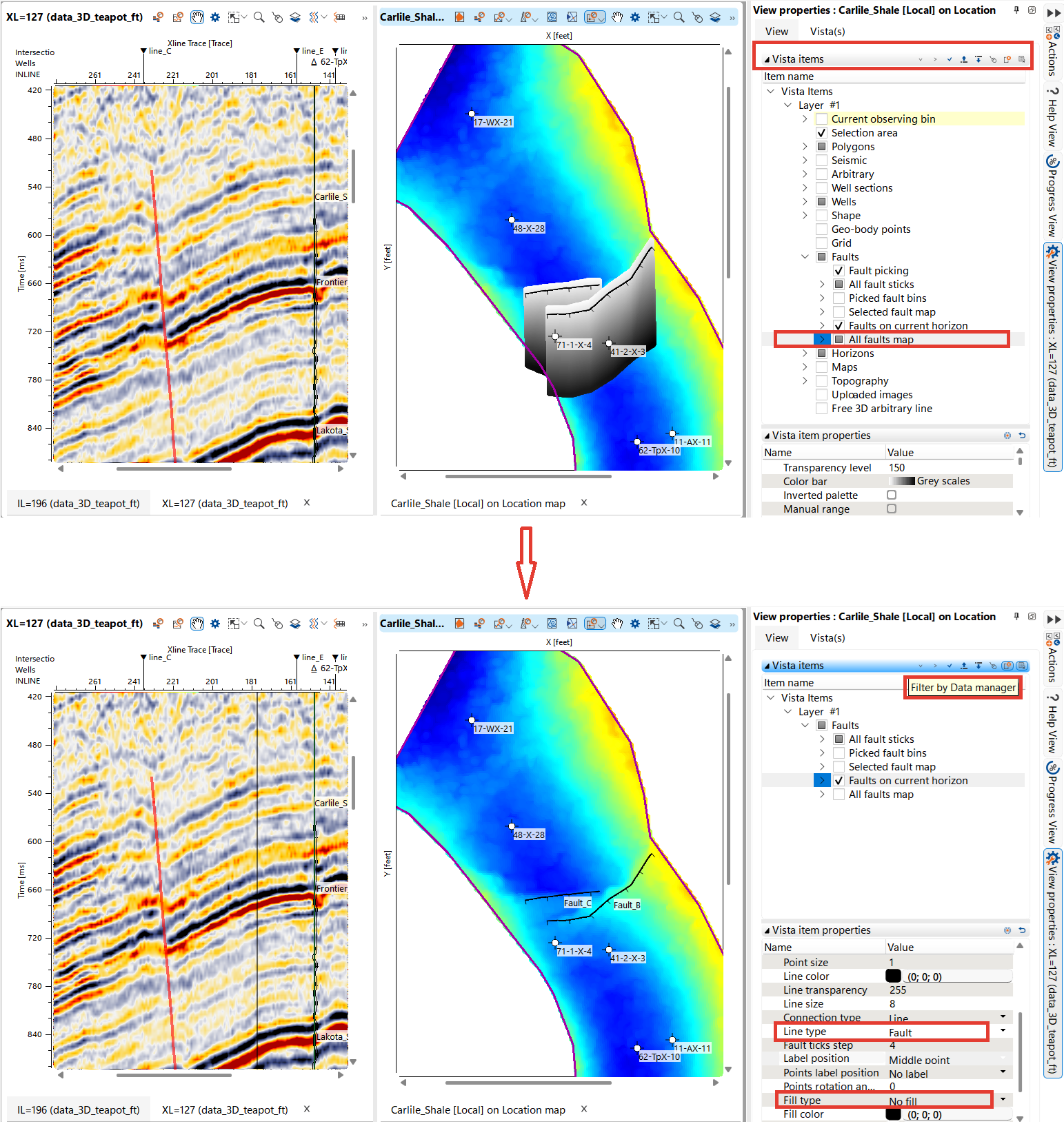
By default, in g-Space, all objects are displayed layer by layer in the map window, so the fault plane projection will be visible on the map. Users can filter and organize objects in the Object tab tools menu located on the top panel.
To display faults on the horizon map as a line, select No fill option in the Object item properties and choose Fault line to create an image similar to the one shown below.
For more details on panel properties, refer to the Object(s) and Visual Settings sections.
To rebuild a horizon map with fault constraints, open the map interpolation settings, set Fault handling to Use selected faults or Use fault model, and configure the corresponding faults. Then, in the Data Manager, right-click the horizon and select Recreate horizon map.
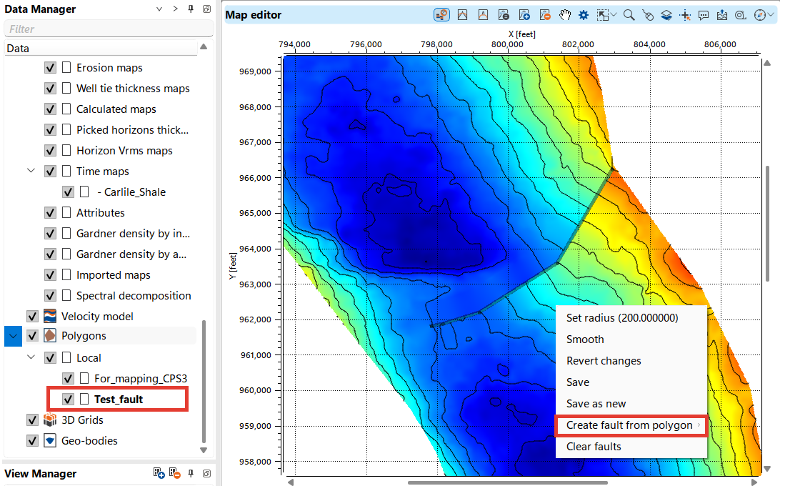
In the g-Space Map Editor, users can create a fault from a polygon. To do this, first create an empty polygon in the Data Manager. Then, draw the polygon on the map at the expected fault location, enabling the Draw fault function. Once you finish drawing by double-clicking, the polygon will resemble a fault, and the map will automatically update.
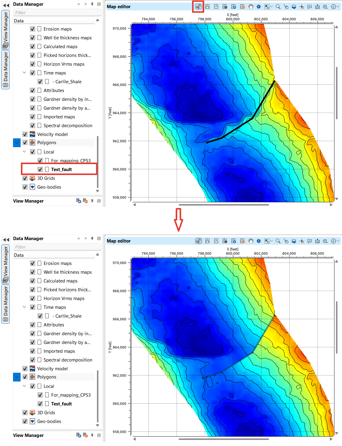
To save the polygon as a fault in the Data Manager, press Alt + right-click and select Create fault from polygon.
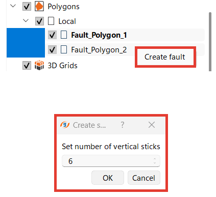
In the Data Manager, you can transfer data from polygons to faults by selecting the desired polygons, holding down the Shift key, and right-clicking. This will bring up the Create fault function in the menu. A pop-up will appear where you need to set the number of sticks for the break. We recommend setting the number of sticks to be no less than the number of polygon points.
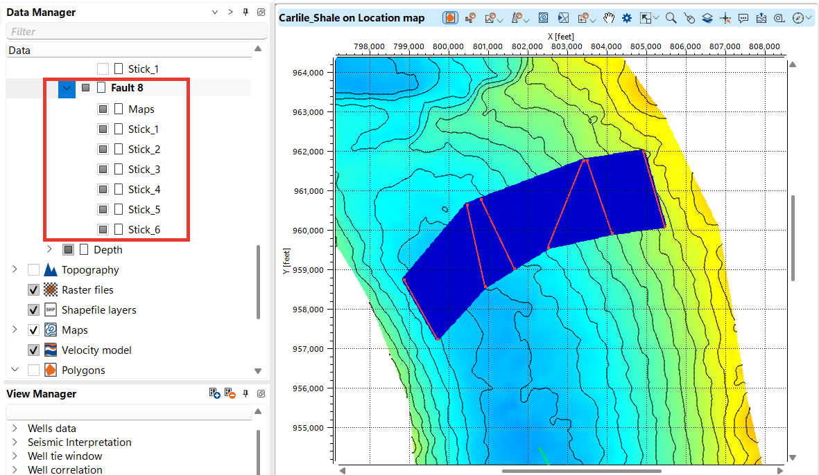
Name this fault and it will appear in the Data manager folder.
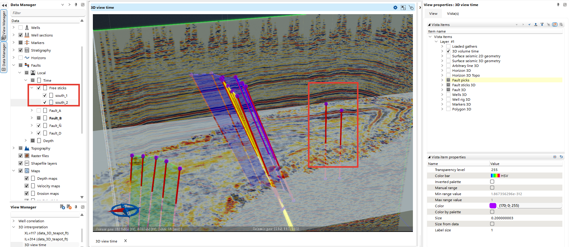
To work with faults in 3D view, you can set up visualization in the form of picks, sticks, fault maps and combine different types of visualization as shown in images below.
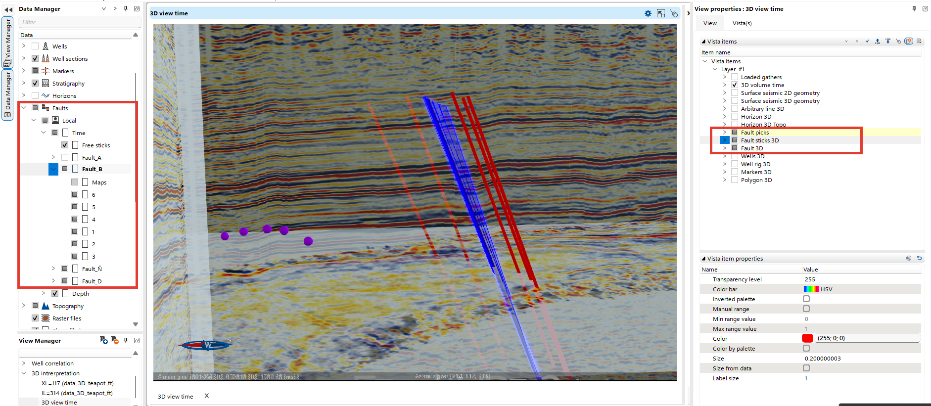
The user can also work with free sticks and customize their visualization.
To export the created faults, use the Faults Management group on the Interpretation bar.