Conceptual Model
The Conceptual Model panel is used to build a structured geological framework from existing project data. It does not store new data – instead it links objects from the Data Manager to geological objects that can later be used in Structural Modeling.
The Conceptual Model is domain-independent: a single framework can reference both Time and Depth data at the same time. The domain is not chosen here – it is applied later, when the framework is used in Structural Modeling, where only the data matching the selected domain is used.
The panel is docked on the right side of the g-Space window, tabbed together with the Data Manager, Object properties and Visual Settings panels. (The View Manager is docked separately, alone, on the left side of the window.)
Conceptual Models in the Project
A project can hold several conceptual models, each with its own name and its own configuration. The combo box in the panel title bar selects the active model: the tree always shows the active conceptual model, and everything that uses the framework, such as Structural Modeling, works with the same active model. The actions next to the selector manage the models themselves:
- New – opens the New conceptual model prompt, where Model name: is pre-filled with the next free default name (Conceptual model 1, Conceptual model 2, and so on). The new model is empty and becomes the active one.
- Rename – opens the Rename conceptual model prompt for the active model.
- Duplicate – opens the Duplicate conceptual model prompt, where New model name: is pre-filled with the name of the active model followed by (copy). The copy repeats the whole configuration of the active model – its objects, their assigned data, Conformity, Direction and Stratigraphy settings, its zones and its linked fault model – and becomes the active one.
- Delete – asks for confirmation and then removes the configuration of the active model only; the source data stays in the Data Manager. Deleting the last remaining model leaves a new empty Conceptual model 1.
Model names must be unique. If the entered name is already taken, g-Space reports it and the prompt stays open so that another name can be entered. A project saved before several conceptual models were supported opens as a single model named Conceptual model 1.
Geological Objects
Create and organize geological boundaries in top-to-bottom order. Each object represents a geological level (a horizon, an unconformity, or an intrusion) within the conceptual framework of the reservoir. Right-click in the tree to Add Object, Add Object Above or Add Object Below a selected object, Rename it, or Remove Object.
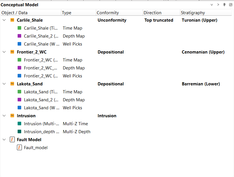
The tree is shown with the columns Object / Data, Type, Conformity, Direction and Stratigraphy. Object rows carry the Conformity and Direction values, while each linked data row shows its detected Type.
Linked Data
Drag objects from the Data Manager and assign them to a geological object. Time and Depth maps, horizon points and horizon maps (Time or Depth), Multi-Z surfaces (Time or Depth), attribute maps, and Markers (shown as "Well Picks" in the panel) can all be linked, so that one geological object combines several data representations. The type and domain of each dropped item are detected automatically and shown in the Type column.
Each object may hold only one item per data type. Dropping an unsupported item type shows a warning and is ignored; dropping an item whose type is already present asks for confirmation before replacing the existing one. Items can also be linked without dragging: right-click an item in the Data Manager and choose Assign to Conceptual Model (or Remove from Conceptual Model). Right-click a linked data row and choose Navigate to Data Manager to jump back to the source item.
Conformity
Define the boundary type for each geological object:
- Depositional – a conformable boundary that follows normal deposition.
- Unconformity – an erosional or non-depositional surface that truncates older layers.
- Intrusion – a body that cross-cuts the surrounding stratigraphy.
Direction
For unconformities, define whether the object is Top truncated or Bottom truncated. This controls how the surface interacts with the layers above and below it during structural modeling. By default no direction is set.
Stratigraphy
Right-click a geological object and choose Set Stratigraphy... to associate it with a chronostratigraphic zone from the project's stratigraphy columns. The dialog shows one cascading combo box per stratigraphy column, from broadest to narrowest. Choose Clear Stratigraphy to remove the association.
When a marker is assigned to a geological object as Well Picks, g-Space compares its age with the project's current stratigraphy. If a matching zone is found and the object has no valid stratigraphy, g-Space fills the object's Stratigraphy value automatically. An existing valid assignment is preserved and can still be changed with Set Stratigraphy....
Zones
When at least two geological objects take part in the layering, g-Space maintains the zones between them automatically. Depositional and Unconformity objects take part; Intrusion objects do not, and zones span across them. One zone is kept above the first participating object, one between each consecutive pair, and one below the last one, so that zone rows and object rows alternate from top to bottom.
A zone is named after the objects that bound it – for example, Object_1-Object_2 – and the open ends of the column are shown as (surface) and (base). A zone row shows Zone in the Type column, leaves Conformity empty and inherits the Stratigraphy of its upper bounding object. If the ages of the two bounding objects are out of column order, the inherited value is marked (check order).
A zone holds one Zone Markers item and one Isochore Map, together with any number of polygons and property maps. Drag the items from the Data Manager onto the zone row: a project zone is taken as the zone markers, a depth map as the isochore map, and other maps and polygons are added to the zone. The same assignments are available by right-clicking the zone – Assign Zone Markers..., Assign Isochore Map..., Add Polygon... and Add Property Map... – and when the project already contains a zone with the same name, the menu offers it directly as Assign Suggested Zone. Choose Rename Zone to give the zone your own name. An item that a zone cannot hold is refused with an Invalid zone assignment message.
Only assigned items are listed under a zone, so an empty zone stays a single row, and a zone is expanded automatically after an assignment.
Adding, removing or reordering an object, and switching its Conformity to or from Intrusion, recalculates the neighboring zones as one step that can be undone at once. Renamed zones and their assigned items survive such a recalculation; when a change would destroy a renamed zone or a zone with assigned data, a Zone destruction confirmation lists what would be lost before the change is applied.
A warning icon in place of the zone icon means that one of the two objects bounding the zone has unresolved inputs – no data assigned, an Unconformity with no Direction, or an assigned item that no longer resolves in the Data Manager, such as a Multi-Z surface whose source item was removed; point at the row in the Object / Data column to read A bounding top of this zone has unresolved errors. While a zone is in this state, its assigned Zone Markers row shows — (top has errors) instead of the name of the item.
Fault Model
Optionally link one global Fault Model to the conceptual model. Only one fault model can be linked; assign it by right-clicking a fault model in the Data Manager and choosing Assign as Conceptual Model fault model. When present, this fault model is preselected as the default in the Structural Modeling wizard, where the fault framework is taken into account when the structural model is built.
Clearing the Model
Right-click an empty area of the panel to clean up the active conceptual model:
- Clear all – removes the whole configuration of the active conceptual model, including every geological object with its assigned data, the zones between them and the linked Fault Model, and returns the panel to its empty state.
- Delete assigned data for all objects – removes the assigned data from every geological object but keeps the objects themselves, with their names and their Conformity, Direction and Stratigraphy settings.
Both actions ask for confirmation before they run. To clear a single object, right-click it and choose Delete assigned data: only the data assigned to that object is removed and the other objects stay unchanged.
Each action appears only when there is something for it to remove. All three affect the conceptual model only – the source items are not deleted from the Data Manager.
See Also