Upscale 3D Grid
Upscale 3D Grid creates a new, coarser 3D grid from an existing structured grid by combining several fine cells into one larger cell. It is used to reduce the cell count of a 3D grid before further modeling or simulation while preserving the essential distribution of a property.
The operation always produces a new upscaled grid in the Data Manager — the original grid is never overwritten. Upscaling is available for structured grids (S-Grids) only; it is not supported for tetrahedral grids.
Purpose
The tool is designed for:
- Reducing the resolution (cell count) of a 3D grid to speed up modeling, visualization and simulation
- Combining several fine cells into one coarser cell along the I, J and K grid directions
- Recalculating property values for the new, larger cells using a chosen statistical rule
- Preparing a lightweight grid as part of a larger grid-preparation workflow
Requirements
- A structured 3D grid (S-Grid) available in the Data Manager. Tetrahedral grids are not supported.
- At least one grid property to upscale (upscaling is launched from a property of the grid)
- Upscaling factors that produce a coarser grid — at least one of the I, J or K values must be greater than 1
Launching the Wizard
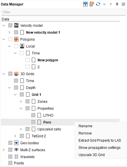
The wizard is opened from the property context menu of a 3D grid in the Data Manager:
- In the Data Manager, expand the target 3D grid and open its Properties folder.
- Right-click the property you want to upscale.
- Select Upscale 3D Grid from the context menu.
The right-clicked property is used as the input, and the resulting upscaled grid contains that single property. The wizard opens as a dialog titled Upscale 3D Grid - <grid> / <property>.
Step-by-Step Guide
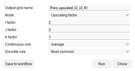
All settings are collected in a single dialog. Configure the output name, the target resolution and the property rules, then run the operation.
Output Grid Name
Output grid name — the name of the new upscaled grid. A default name is proposed from the source property name with an _upscaled_I<i>_J<j>_K<k> suffix that reflects the chosen factors (for example Porosity_upscaled_I2_J2_K1). The name must not be empty and must not match an existing grid; a unique name is generated automatically if a clash occurs.
Output Resolution
Mode — defines how the new cell size is specified:
- Upscaling factor — how many original cells are combined into one larger cell along each direction.
- Target cell size — the desired output cell size; the factor is derived automatically from the input cell size.
When Upscaling factor is selected, set the per-direction factors:
- I factor — cells combined along the first horizontal grid direction (default 2).
- J factor — cells combined along the second horizontal grid direction (default 2).
- K factor — cells combined vertically, layer to layer (default 1).
When Target cell size is selected, set I target cell size, J target cell size and K target cell size instead. The visible controls switch automatically with the selected mode.
The K factor is kept at 1 by default because vertical layering is usually geologically meaningful. At least one of the I, J or K factors must be greater than 1, otherwise the grid would not be coarsened.
Property Upscaling Rules
The value of each new, larger cell is calculated from the fine cells it covers. The rule that is applied depends on the property type — continuous (Petrophysical) or discrete (Facies):
Continuous rule — applied to continuous properties:
- Average — mean of the covered cell values (default).
- Median — middle value, reducing the effect of outliers.
- Minimum — lowest covered value.
- Maximum — highest covered value.
Discrete rule — applied to discrete (categorical) properties:
- Most common — the most frequent code among the covered cells (default).
- Dominant — the prevailing code among the covered cells.
Running the Upscaling
Press Run to create the upscaled grid immediately, or Save to workflow to store the operation as a workflow step (see below). Use Close to dismiss the dialog. When Run finishes, the new grid appears in the Data Manager.
Adding to a Workflow
The Upscale 3D Grid operation can be added to a Workflow so it can be reused and re-run later:
- Configure all settings in the wizard as usual.
- Press Save to workflow instead of Run. A workflow step of type Upscale 3D grid is appended, with all selected parameters (mode, factors or target cell sizes, and property rules) stored inside it.
- Re-run the step from the workflow at any time, or reopen it to edit the parameters.
This makes the operation a repeatable building block in a larger grid-preparation workflow.
Results
- A new upscaled 3D grid is added to the Data Manager; the original grid is unchanged.
- The grid geometry is coarsened according to the selected factor or target cell size, with the cell step scaled by the factor along each direction.
- Continuous properties are recalculated with the selected continuous rule; discrete properties are recalculated with the selected discrete rule.
- Undefined cells remain undefined when a new cell has no valid input values; otherwise the output value is computed from the valid covered cells.
- Multi-zone grids are supported — each zone is upscaled independently, preserving the zone structure.
- The upscaled grid and its property can be displayed in the 3D View and section views, and are saved and restored with the project.
Recommendations
- Keep K factor at 1 unless you specifically want to merge layers vertically, so the original vertical layering is preserved.
- Start with a modest lateral factor (for example I = 2, J = 2) and review the result before coarsening further.
- Use Average or Median for continuous petrophysical properties, and Most common for facies and other categorical properties.
- Use Target cell size when you need the output grid to match a specific cell size rather than a fixed combining factor.
See Also