Structural models
The Structural models branch contains saved depth- and time-domain models, grouped by user and domain.
Right-click the branch, a user folder, or a Depth/Time folder and choose Create new to open the Structural Modeling wizard. Starting from a domain folder presets that domain.
Right-click the Structural models branch and choose Slicer to drive the 3D slicing plane from the built models. Show slicer is a check item that turns the plane on and off and is always available; Edit slicer parameters and Recalculate slicer parameters are enabled only while the slicer is shown. When you switch the slicer on from this branch, or it was last driven from another branch, its extent is computed automatically from the layer volumes of every built structural model — the objects under each model's Layers folder — so at least one model must have been built with Generate layers from horizon pairs enabled; otherwise nothing is shown. Recalculate slicer parameters recomputes that extent from the same models and opens the slicer parameters wizard, while Edit slicer parameters opens that wizard for the current slicer without recomputing. There is a single shared slicing plane, so driving it here re-sources the same plane that the Geo-bodies and 3D Grids branches use; see Geological modeling for what the Slicer mode shows.
A built model organizes its results into these subfolders:
- TIN Maps — modeled horizon surfaces
- Faults — fault surfaces used by the model
- Intrusions — modeled intrusion surfaces
- Layers — volumes generated between horizon pairs
- Fault Blocks — separate blocks generated from a selected fault model
TIN Maps, Intrusions and Layers are always present under a built model and stay visible even when they contain nothing, so an empty Layers folder means that layer generation produced no volumes, not that the model itself is incomplete. Faults and Fault Blocks appear only when the model actually produced fault surfaces or fault blocks, so a model built without a fault model shows neither folder.
To give every object in a folder a different automatically generated color at once, right-click the model's TIN Maps, Faults, Intrusions or Layers folder and choose Colorize. The new colors are applied immediately, without a dialog, and repaint the Data Manager and views that use solid object colors. A TIN map with Color by palette enabled in the 3D view keeps its Z-based colors. On the Faults folder the command usually appears to change nothing, because each fault keeps the color it takes from the fault model rather than the one stored with the structural model. An individual fault under a model offers only Extract fault data and no Set color, so change a structural model's fault colors on the fault model, or on the interpreted fault of the same name, and not on the model; see Fault model. Colorize is not offered on the Fault Blocks folder; fault blocks are given distinct colors automatically when the model is built, and Set color on an individual fault block changes one of them.
The blocks are numbered as they are built, so the folder lists Fault block 1, Fault block 2 and so on.
Right-click a single fault block for its own commands:
- Set color — replaces the color the block was given automatically when the model was built.
- Rename — opens the Rename fault block dialog. The name it offers starts with the model name, which the Data Manager does not repeat in the tree, and a name already used by another block of the same model is refused with a message.
- Delete — removes that block.
- Isolate — shows the block on its own by clearing the check boxes of the other blocks in the folder.
On the Fault Blocks folder itself, Delete removes every block of the model at once.
For an individual block, Delete asks you to confirm deletion of the named fault block; decline to keep it. Delete on the Fault Blocks folder removes every block without confirmation. Neither command changes the model definition, so running the model again with Generate fault blocks enabled rebuilds the full set.
To turn modeled fault surfaces into points, right-click the model's Faults folder and choose Extract fault data to include every fault in it, or right-click a single fault under that folder to include only that fault. The command opens the Extract fault data dialog with an Output name already filled in from the model name for the folder and from the fault name for a single fault; Points is the only Output data type, so the extraction always produces a point set under Points in the Data Manager. See Fault model for the dialog options and for the same command on a fault model.
To reuse layer volumes as ordinary geobodies, right-click the model's Layers folder and choose Save as geobodies to copy every layer in that folder into the Geo-bodies branch, or right-click a single layer and choose Save as geobody to copy just that one. Each copy takes the layer's geometry, color, age and class, and the structural model keeps its own layers, so the copy is an independent object — clearing the layer's check box does not hide the geobody, and clearing the geobody's check box does not hide the layer. From then on the copy behaves like any other geobody: it has its own check box in the Data Manager, an entry in the 3D view and in the Visual Settings panel, and the standard geobody actions.
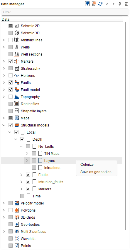
A copy is named after the layer as the Data Manager shows it. In that name a slash, a backslash, an opening square bracket, a space or a tab becomes an underscore and a closing square bracket is dropped, repeated underscores are collapsed, and a leading or trailing underscore is removed, so a layer shown as Object_1/Object_2 [Block 1] gives a geobody named Object_1_Object_2_Block_1. When a geobody of that name already exists, the Geobody name collision dialog offers Overwrite existing objects, Create unique names and Cancel (Overwrite existing object, Create unique name and Cancel for a single layer). A unique name is made by appending a space and a number, as in Object_1_Object_2_Block_1 1 and then Object_1_Object_2_Block_1 2. For the folder command the question is asked once, before anything is written, and the answer applies to every colliding name, so Cancel leaves the project unchanged.
A layer whose geometry is incomplete is skipped instead of converted: Save as geobody reports that the layer failed because its geometry is invalid and creates nothing, while Save as geobodies lists such layers under Failed in the summary it shows when it finishes. That summary also reports how many geobodies were saved, how many were overwritten and which ones were renamed to keep names unique. On an empty Layers folder, Save as geobodies reports that no layer objects are available to save as geobodies.
Each object under TIN Maps, Faults, Intrusions, Layers and Fault Blocks is listed in the Data Manager with its assigned color filling the object icon, so horizons, faults, intrusions, layers and fault blocks can be told apart by color directly in the tree. By default, an object's assigned color is also used in the 3D and section views; a fault takes its color from the fault model. An object with no assigned color keeps the plain icon, and some interface themes show plain icons throughout.
Every object in these subfolders has its own check box. Select or clear a check box to show or hide just that object in the 3D view and on section views; the check box on the Structural models branch hides the whole set. The same objects are listed under Structural model 3D on the Object(s) tab of the Visual Settings panel, and that list stays in sync with the Data Manager check boxes.
The Structural model 3D item also has a Display mode property that limits what the model shows in the 3D view: Full structure (default) shows every object of the model, Surfaces only shows only the modeled horizon surfaces from TIN Maps and hides intrusions, layers and fault blocks, and Faults only shows only the fault surfaces. The mode is set on the parent Structural model 3D item and applies to all of its objects, so a cleared check box always wins: the mode only limits what the selected objects may show. The chosen mode is stored with the view. Display mode is a 3D view property and is not available for section views.
In the time or depth 3D view that matches a structural model, open Visual Settings, choose the Object(s) tab, expand Structural model 3D, and select the modeled horizon surface you want to color. The surface is listed under TIN Maps in the Data Manager. Turn on Color by palette to color it by vertex Z from that TIN map's minimum to maximum Z. Choose the palette with Color bar (Jet by default), and use Inverted palette to reverse it. Color by palette is off by default; clear it to use the solid Color again.
The same models are also displayed on inline, crossline and arbitrary line sections in both domains, where they are listed under All structural model on the Object(s) tab of the Visual Settings panel. Modeled horizon, intrusion and fault surfaces are drawn as their intersection lines with the section, while Layers and Fault Blocks are drawn as translucent filled bands that are split where the volume pinches out. Select a layer or fault block under All structural model to restyle its band: Object item properties then offers Fill type (No fill, Solid, a hatch pattern or a gradient), Fill color, Fill color 2 for the second color of the gradient fill types, and Transparency level, which sets how translucent the band is; the band is redrawn immediately. By default a band is solid-filled in the object's own color and translucent. Each choice is kept per object and re-applied whenever the section is rebuilt, so a fill or transparency change is no longer lost when the view refreshes or you step to another line.
A model is displayed only in the views that match its own domain: a model stored in a Depth folder in the 3D view depth and on depth sections, and a model stored in a Time folder in the 3D view time and on time sections. No time-to-depth conversion is applied, so a time-domain model never appears in a depth view.
Double-click a model, or right-click it and choose Open, to restore its settings in the wizard. Only one model can be open in the wizard at a time, so close the wizard before opening another one. Use Run to rebuild or update its results and Save to store changed settings without running.
Other model actions include Rename, Delete and Verify 3D model.
Several models can be removed in one step. Select them in a Depth or Time folder, right-click the selection and choose Remove, the only command offered for a multiple selection. A single confirmation, "Remove N selected structural models?", names the number of selected models; answer No to leave everything unchanged. Each model is then removed exactly as Delete removes a single one, so any Multi-Z surfaces published from it and any uncertainty realizations built from it disappear with it, and the Data Manager, the 3D view, the inline, crossline and arbitrary line sections in both domains, the Location map and the Visual Settings object lists of those views are refreshed at once, so the deleted geometry and its object items disappear immediately and no view or project has to be reopened. The command applies to the model entries only, not to their TIN Maps, Faults, Intrusions, Layers or Fault Blocks folders or to the objects inside them, and no dependency warning is shown here; that extra confirmation belongs to removing fault models (see Fault model).
See Also