Receiver motion correction
Calculating time variant positional errors and correction
Theory
In marine seismic data acquisition, we've streamers/cables are towed behind the seismic acquisition vessel/ship. These streamers/cables are towed below the sea water at ~6 m depth. Streamer/cable towing depth is not constant and it varies depending on the survey and sea conditions. If the sea condition is rough/choppy, the streamer/cables may be lowered to minimize the noise.
During the entire survey period, these streamers/cables are moving in the direction of the in-line direction. Because of this, it will create time variant positional errors which leads to travel time difference . As per the original survey parameters, the channel/receiver should be at a particular location however due to the continuous movement of the streamer/cable the channel/receiver will be at a different location. Because of the timing difference, it will create horizontal striping on the seismic data. To compensate the time difference, we calculate and apply receiver motion correction.
For the receiver motion correction (RMC), we take the vessel speed as an input. These time variant corrections are calculated for a given sample as
- Multiply receiver interval with previous sample number. This gives us the distance. A = RP Interval*Sample Number
- Multiply sample interval with vessel speed. B = Sample interval * Vessel speed
- Divide A by B. C = A/B
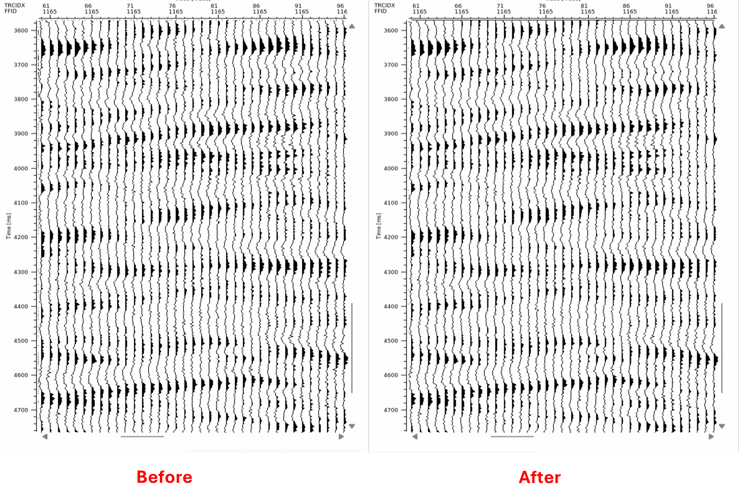
Receiver motion correction changes are very subtle and very negligible however they are important to correct the positional errors.
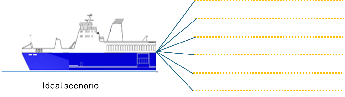
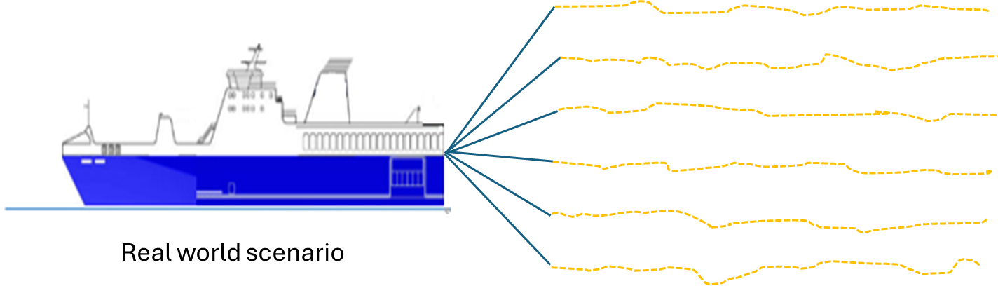
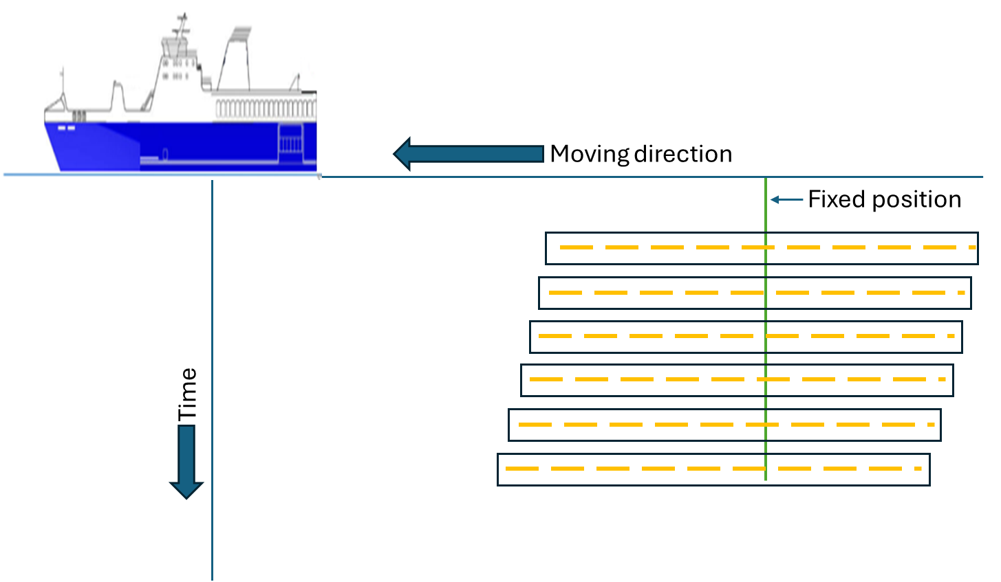
In the below image, the receiver/hydrophone is shifting towards the left from the fixed position (Green vertical) as it is moving in the in-line direction. As the time changes/increases, the receiver/hydrophone position also changes. These slight positional errors are computed based on the vessel speed, receiver interval, sample interval and sample number.
Input data
Input gather
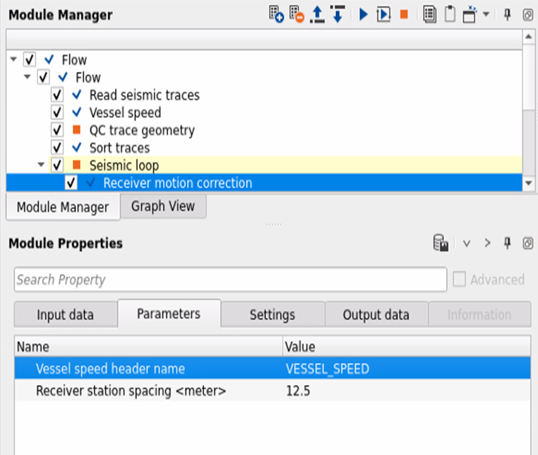
Connect/reference to the Input gather. If it is inside the Seismic loop, it will automatically connects the output gather of the previous module to the input gather of "Receiver motion correction" module.
Parameters
Vessel speed header name
Specify the header name which was generated using "VESSEL SPEED" module.
Receiver station spacing
Specify the receiver interval.
Settings
Auto-connection
By default Yes (Checked)
Number of threads
One less than total no of nodes/threads to execute a job in multi-thread mode.
Skip
By default, No (Unchecked). This option helps to bypass the module from the workflow.
Output data
Output gather
This module outputs receiver motion corrected output gathers
Examples
Here is an example workflow.
The methodology of calculating the receiver motion correction.
- Calculate the time stamps from the original field data i.e. SEGD
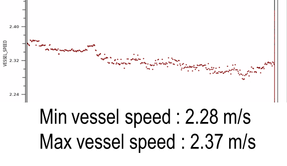
- Input these time stamps to calculate the Vessel speed.
- Smooth vessel speeds.
- Use the vessel speed information to calculate the correction for the moving receivers.
Video lesson
YouTube video lesson, click here to open [VIDEO IN PROCESS...]
Related articles
Yilmaz. O., 1987, Seismic data processing: Society of Exploration Geophysicist
 * * * If you have any questions, please send an e-mail to: support@geomage.com * * *
